With experience in PCB fabrication, assembly and rework, and state-of-the art equipment, ElectraTech’ rework technicians use the proper materials and methods to troubleshoot, diagnose, and rework a wide variety of issues, like SMT Component, ICs and BGAs removal and replacement, Component salvage, Optical verification services & X-ray inspection.
Our capabilities for PCB & BGA Rework:
BGA Component Reballing Including BGA component reball service to replace lead-free solder balls with leaded solder balls for high-rel applications.
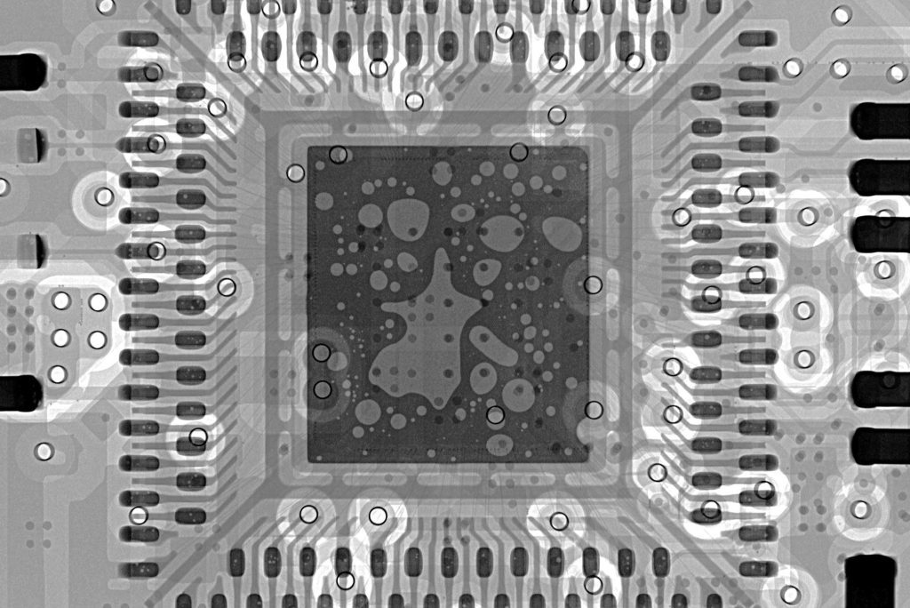
BGA Component Rework Including BGA rework, BGA component x-ray services, repair of damaged BGA pads and solder mask damage.
BGA Component Site Modification This unique procedure uses copper ribbon that fits under the BGA component to provide an electrical path for modification.
Base Board Repair and Rework Including repair damaged circuit base board laminate, delamination, warp, hole damage, burns, and solder mask damage.
Circuitry and Plated Hole Repair Including repair of damage to circuitry and plated holes, plus repair of damaged plated holes with inner layer connections.
Coating and Marking Rework Including rework of conformal coatings and solder mask, and repair of circuit board legend and markings.
Component Rework Including removal or replacement of surface mount and through hole components, connectors and more.
Component Salvage and Harvest Includes removal and salvage of BGA and surface mount components, connectors and many other component types.
Engineering Change Services Including engineering changes, upgrades, modifications, jumper wires, circuit cuts, and many other procedures.
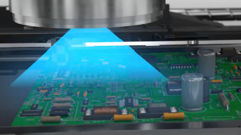
Inspection Services Including BGA component and circuit board x-ray inspection services using high-end Dage inspection systems.
SMT/BGA Pad Repair Including repair of damaged or missing surface mount pads, BGA pads, and BGA pads with integral vias.
PCB Clone & Reverse Engineering
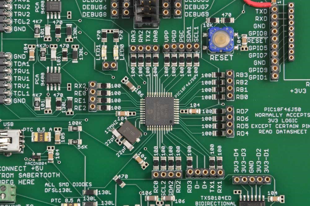
We are the provider of the only system in the world that can take a physical circuit board and fully reverse engineer it to provide complete manufacturing CAD data and even native format schematics. Our system includes the ability to capture precise form, fit and function for all layers of the PCB, including all inner layer geometries, drill, drill plating and layer thickness, cut-outs, outline, silkscreen, and even blind or buried vias.
Data generated from PCB Reverse Engineering can be used either to manufacture replacement parts, or provide insight in repairing existing parts when schematics may not be available.
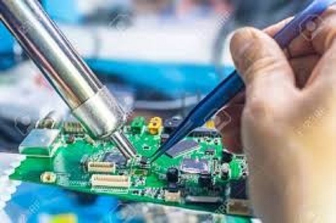
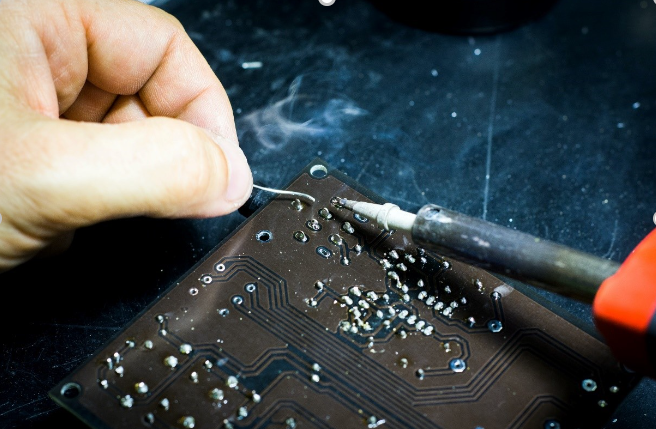
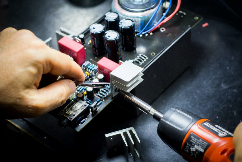
Manual Soldering
This step is achieved manually by professional engineering staff. Engineers need to quickly, yet precisely place componentson corresponding positions based on client’s PCB design files. Component placement must conform to regulations and operation standards of thru-hole mounting process to guarantee high quality end products.
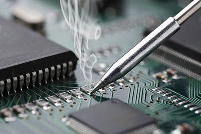
Wave Soldering
The automated version of manual soldering is wave soldering. In this method, once the PTH components are placed on the PCB, the PCB is put on the conveyer belt and is moved to specialized oven. Here a wave of molten solder is splashed on the PCB bottom layer where the components leads are present. This will solder all the pins at once
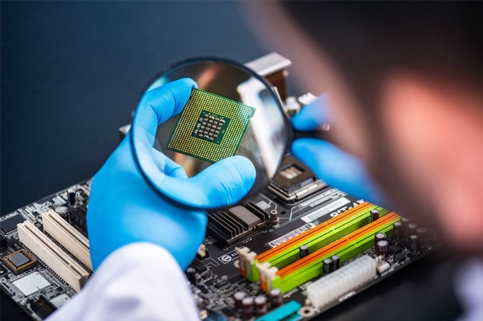
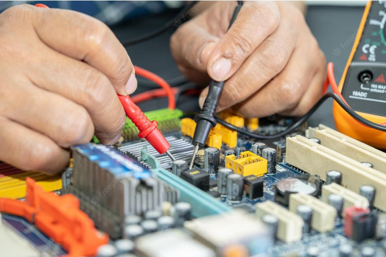
Final Inspection and Functional Test
The through-hole components are commonly found on many PCB boards. These components are also known as Plated through Hole (PTH). These components have leads that will pass through the hole in the PCB. These holes connect to other holes and vias by means of copper traces. When these THT components are inserted and soldered in these holes, then they are electrically connected to other hole in the same PCB as the circuit designed. These PCBs may contain some THT components and many SMD components so the soldering method as discussed above in case of SMT components like reflow soldering will not work on THT components. So the two main types of THT components soldering or prototype pcb assembly are Manual soldering and Wave soldering.
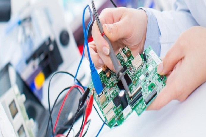
This test is to check the functionality and electrical characteristics of PCB and to verify current, voltage, analog and digital signals as described in the requirements of PCB and circuit design. If any of the parameters of the PCB shows unacceptable results, then the PCB is discarded or scrapped as per the company standard procedures. Testing phase is very important because it determines the success or failure of the entire process of PCBA.
Automatic THT Assembly line
We provide automatic THT component assembly using Axial and Radial assembly machines.
Due to the products introduced by the developing technology in our Daily lives, electronic board designs have started to contain more SMD components. However, THT components are still frequently used.
THT assemblies are preferred especially for passive elements with high power and capacitance values which are difficult to install by automatic assembly systems and have to be placed using manual assembly line.
With our Axial and Radial THT assembly machines, we provide assembly solutions that meet all the needs of our customers.